
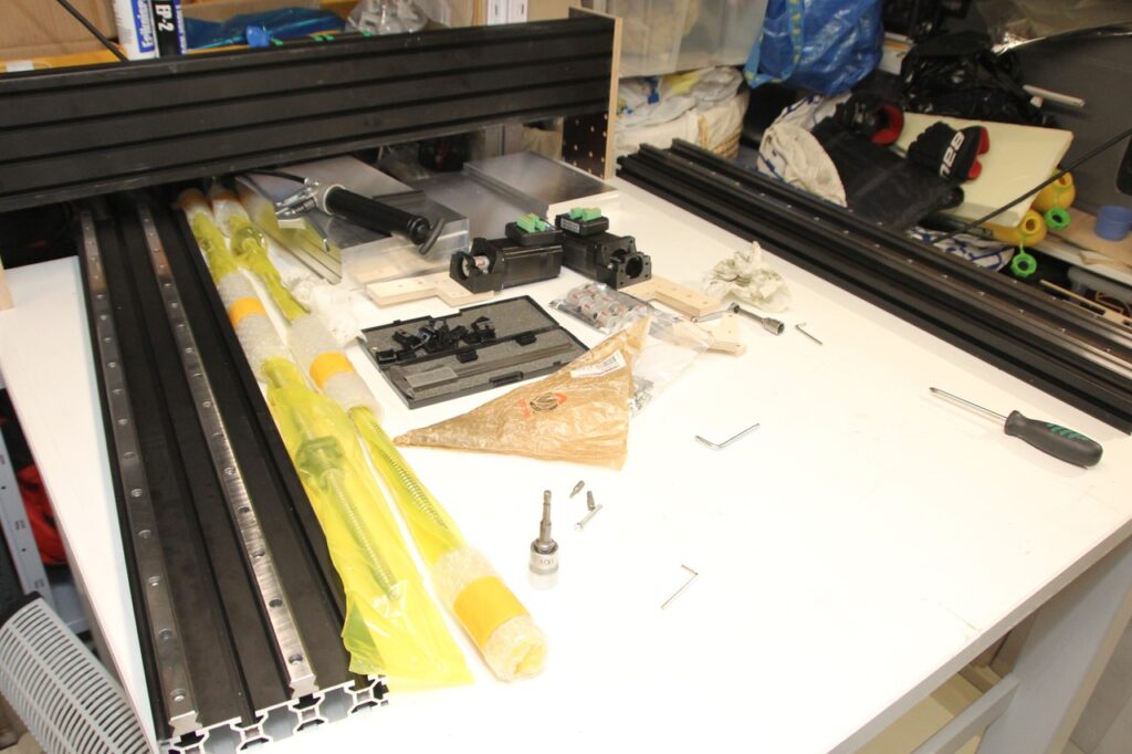
Assembling the CNC Machine using Prototype gantry plates.
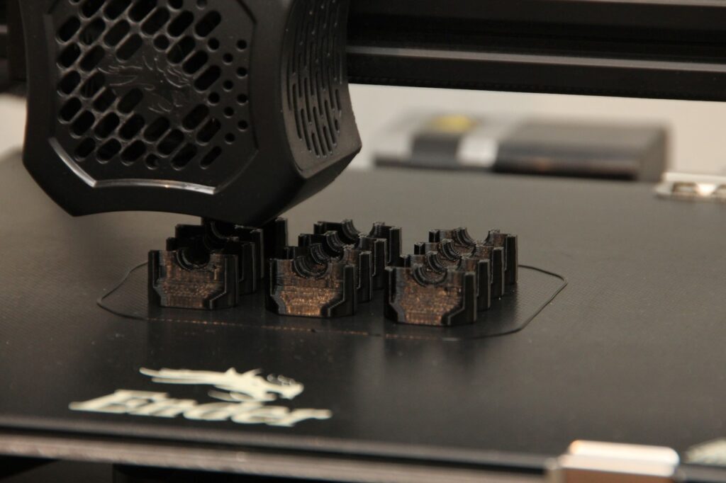
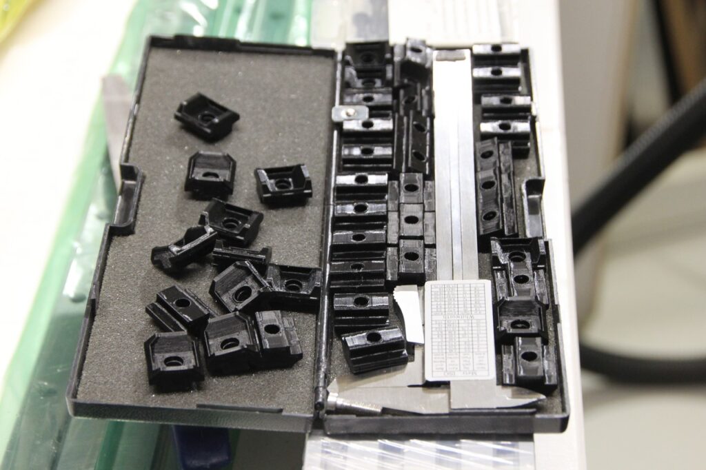
Since the steel T-nuts from China is on their excursion trip somewhere who knows where, i printed t-nuts with my 3d printed. The idea is to use the openbuilds tee-nuts ordered from Nettiverstas. So the plastic t-nut goes into the 40160 Ratrig profile slot and underneath the t-nut there is an steel tee-nut which has threads for a M5 bolt.
A set of 20 t-nuts took ~7 hours to print. I placed one t-nut on every 2nd rail hole because this is just a prototype stage. When i get the steel t-nuts, i probably use one per rail hole.


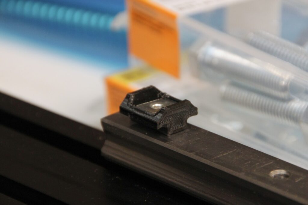
The 16mm long bolts were just enough to hit the threads so that it was not forced to buy 20mm bolts just for prototyping purposes, which saves some money. So below image set shows the rail assembly. First the 3 nuts are inserted inside the profile (with the rail) and after that the rail was glided two holes at a time and a nut was placed in place and glided further until whole rail was on place. Same for both rails. Then for the X axis (images below) the 10mm rail measurement jig (made earlier) was used and aligned the rails 10mm from the edge on bot upper and lower rail and tightened them in place. The nuts were able to handle the momentum of tightening but at beginning on each bolt there was some kind of click, like if something was broken on the nut… Anyway after that the tightening was proceeding well, no problems there… Maybe when disassembling the rails, the clicking sound will be revealed. 😅


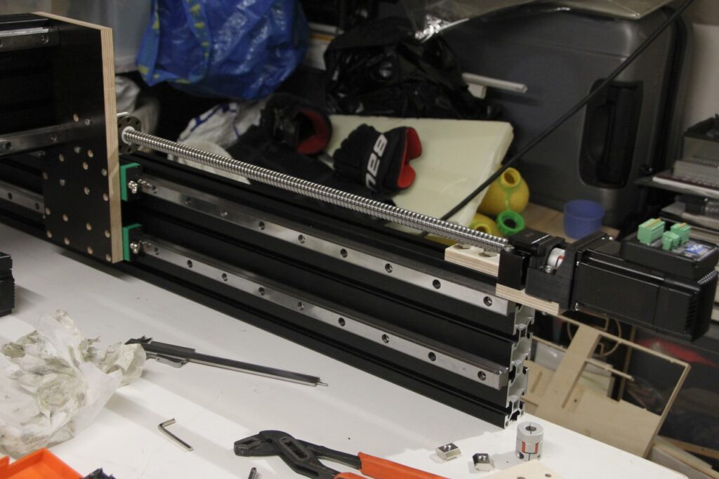
X-Axis was finally up and seemed very rigid and stiff with angles and everything aligned perfectly.

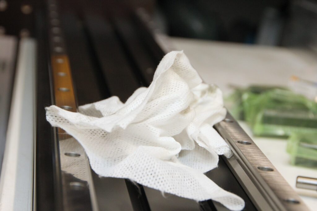
After the X-axis assembly the Y axis rails was cleaned (X axis was cleaned earlier) and started to put the Y-axis rails into place using the 10mm measurement jig only on the upper rail and tightened the upper rails. The lower rail was left loose in order to be able to fit the gliding blocks when assembling X axis on y Axis. Also as a side note, its a good idea to install the X axis so that it only has one block on, then slide an other block and tighten it. Do likewise on the other side. And finally when they are aligned, slide in the rest of the gliding HGH blocks. Otherwise you may end up with a steel bearing ball catastrophe in your workshop.
So, both of the upper rails blocks were installed (better to install one at a time as explained earlier). After a slight struggle the blocks was on the rail and the other side was also lifted to the rail. Then the X carriage bar was glided back and fort and at same time while the process aligned the blocks, the block bolts were tightened.
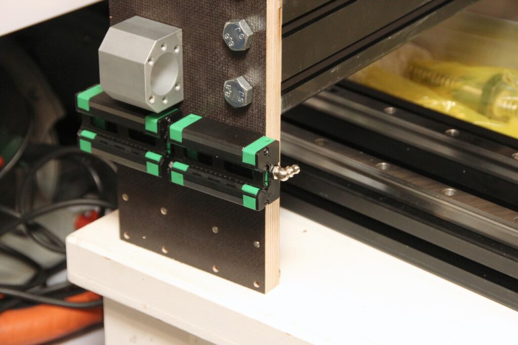
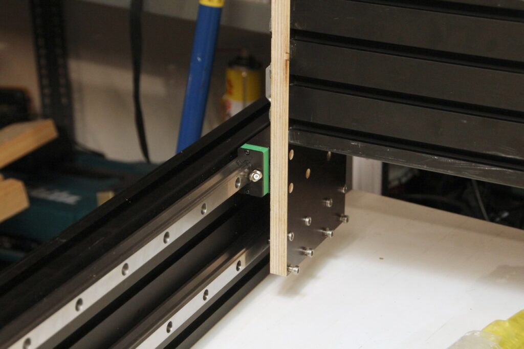

After both sides was tightened one block was glided at a time and tightened it to the y gantry plate, one by one. With only 2 blocks per side, the X carriage moved slightly better than with all 4 blocks installed, so it probably needs to be adjusted so that the frame will be more square. No dial indicator was used to align the rails or blocks but maybe ill do that with the final version. I just wanted to see how well everything can be aligned only with the precision of my current small CNC machine. And as far, seems very good. It would be maybe a good idea to make a rectangular measurement jig that comes between y axis rails so that distance is a same on does not vary on the 1 meter range since I already have aligned the upper rail to 10mm from the edge. The Y axis lower rail, as you may notice is not in the lowest slot, so the 10mm measurement jig cannot be used for that.
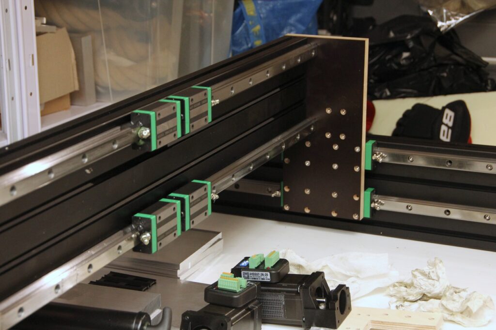

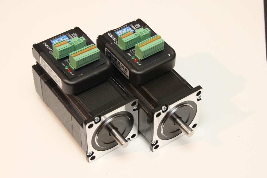
As you may notice also the iHSS57-36-20 hybrid closed loop stepper motors arrived, which was ordered from AliExpress. They were roughly half the price (150€ + a 30€ customs fee) of the other 2 motors (same model) that was ordered from sorotec.de, which is btw a very good place to order CNC bits from! If your from Finland, Nettiverstas also offers a good variety of CNC bits.
One of the motors had some humidity on the shaft and outer body, so the motors were left drying out from the box a couple of days before hooking them up with some electricity. Also seems like someone from the customs, or some other party has opened the box with a knife a little to eagerly and there is a knife scratch on the left side of the left motor. You can see it if you take a close look.
That’s it for now. Next up will be to figure out how to grease the blocks since that has been a hard task for me… Other upcoming tasks are, Planning of the X gantry plate (which holds the rails for Z axis carriage). Also some re-planning of the y gantry plate outer shape from rectangular to some finer shape will be considered. It will slightly reduce the overall weight of the machine and so on (not much, just a little bit).

