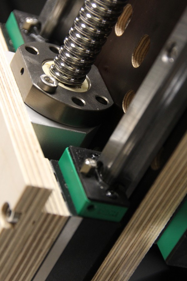
Assembling the Z-Axis Gantry Plate prototype
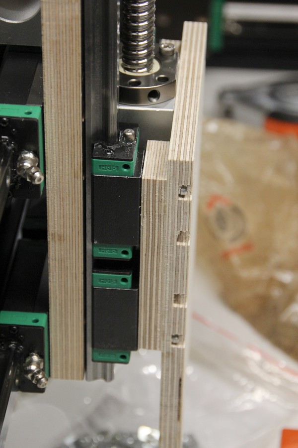
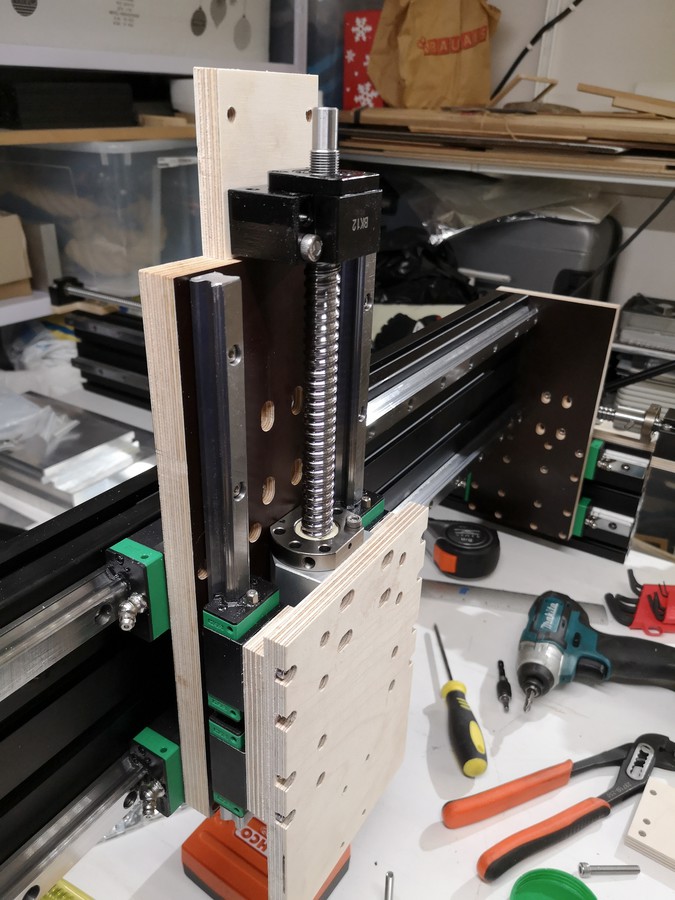
The gantry plate for the Z-axis worked out well. One problem that was encountered was that one of the HGR15 block threads was miss placed on the factory and was not centered correctly. This is not a problem in other way than that the block will be on slightly different height compared to the block on the opposite side.
The Nut hosing is max 1mm but probably less than 1mm away from the X-axis gantry plate. This means that when i use 10mm aluminum plate insted of this 12mm plywood, i need to make a pocket on the X axis plate to allow the nut hosing move without hitting the plate.
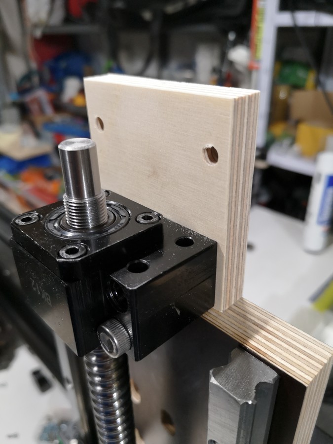
With this prototype there is one problem that must also be re-designed on the X axis plate -> how the motor and the BK12 bearing blocks will be mounted. I also need to print new motor mounts and route the X axis ball screw mount end plates.
First idea is just to extend the X gantry plate with a narrower bit raising upwards from the top of the plate. But this is for the final aluminum version so i need to think of something temporary now…

EDIT
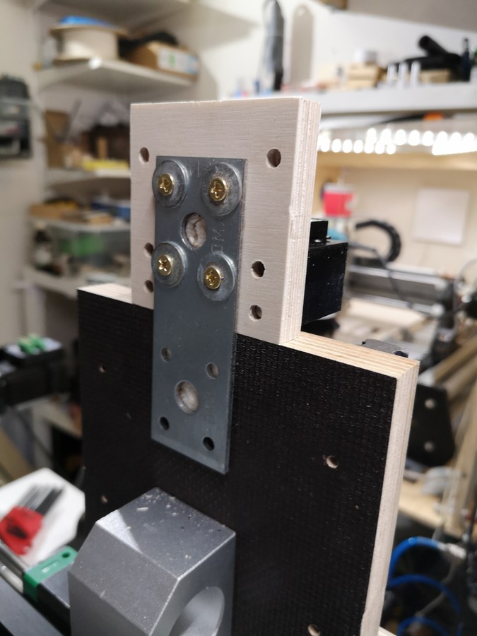
Here is the nasty fix for the design shown above.


